In 1969, NASA’s Apollo 11 Lunar Module touched down on the Moon’s surface, forever changing human history. Here, we’ll dive deep into its crucial specs, the groundbreaking tech behind it, and much more. This article will delve into the fundamental aspects of NASA’s Apollo 11 Lunar Module (LM), providing key insights and facts about this groundbreaking spacecraft.
The Lunar Module (LM)
Overview
The Lunar Module (LM), originally known as the Lunar Excursion Module (LEM), was a spacecraft that allowed Apollo astronauts to land on the Moon. Despite the name change, it was still pronounced “lem.”
Parts of the LM
The LM had two major parts:
- Descent Stage: Used to land on the Moon.
- Ascent Stage: Used to lift astronauts back into lunar orbit.
These stages were carried to the Moon by the Command Service Module (CSM), which was twice the mass of the LM and carried astronauts to and from Earth.
Flight Tests
Before Apollo 11’s successful Moon landing in July 1969, the LM was tested:
- Apollo 9: Tested in Earth orbit.
- Apollo 10: Tested in lunar orbit.
LM Achievements
In total, six LMs landed on the Moon between 1969 and 1972, allowing 12 astronauts to walk on the surface. The last three missions carried a Lunar Rover Vehicle (Moon Buggy) for longer stays on the lunar surface.
Unique Characteristics
The LM was the first true spacecraft, as it could operate only in outer space. It was incapable of flight through Earth’s atmosphere and was discarded after each mission.
Reliability
Most reliable component: No LM ever suffered a failure that affected a mission. During the Apollo 13 crisis, the LM Aquarius exceeded its design limits, maintaining life support for astronauts after an explosion damaged the Service Module.
Size of the LM
The actual LM was:
- Height: 17.9 ft (5.5 m).
- Diameter: 14.0 ft (4.3 m).
- Landing gear span: 29.75 ft (9.07 m).
The model on display is one quarter the size of the actual LM.


Apollo 11 Lunar Module: Eagle
Descent Stage
- Carried fuel and equipment for landing
- Served as launch pad for Ascent Stage
- Contained scientific equipment
- Had four legs with shock-absorbing struts
Ascent Stage
- Crew compartment for two astronauts
- Contained life support systems
- Had rocket engine for lunar liftoff
- Docked with Command Module after ascent
Key Facts
- Nickname: Eagle
- Total weight: 16,448 kg (36,260 lb)
- Height: 7.04 m (23.1 ft)
- Crew: 2 astronauts
- Time on lunar surface: 21 hours, 36 minutes
The Lunar Module’s Two-Stage Design and Function
The Lunar Module (LM), often referred to as the Lander, was a two-part spacecraft engineered to detach from the Apollo Command and Service Module. Its main objective was to transport astronauts to and from the lunar surface.
Armstrong’s Manual Piloting During the Landing
When it came to landing the Eagle in the Sea of Tranquility, Neil Armstrong took matters into his own hands. He manually steered the LM around a terrain riddled with boulders to secure a safe landing.
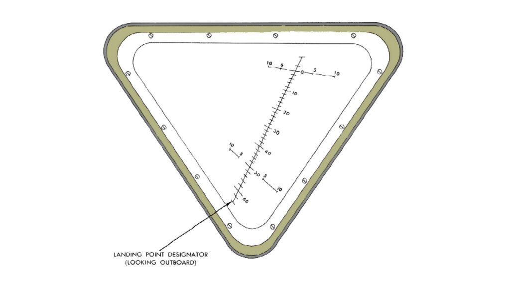
What is the Grid Pattern in the Lunar Module’s Window? Understanding the Landing Point Designator (LPD)
Discussion on the Design and Functionality of the Apollo Lunar Module
If you’re fascinated by the Lunar Module and its crucial role in the Apollo missions, you’ll definitely want to listen to this conversation about the LM below.
Explore a detailed conversation above about the Apollo Lunar Module’s design, key components, and functionality. Learn how the LM enabled astronauts to land on the Moon, featuring insights on its ascent and descent stages, crew compartment, landing gear, and critical subsystems.

The Historic First Moon Landing
Making its first historic touchdown on July 20, 1969, the LM proved its mettle. Generally, the descent stage remained on the Moon, while the ascent stage was deliberately crashed into the lunar surface after its return to the Command Module.
Apollo 11 Mission: Key Facts
Apollo Lunar Module and CSM Names
Apollo 9
LM Name: Spider
CSM Name: Gumdrop
Apollo 10
LM Name: Snoopy
CSM Name: Charlie Brown
Apollo 11
LM Name: Eagle
CSM Name: Columbia
Apollo 12
LM Name: Intrepid
CSM Name: Yankee Clipper
Apollo 13
LM Name: Aquarius
CSM Name: Odyssey
Apollo 14
LM Name: Antares
CSM Name: Kitty Hawk
Apollo 15
LM Name: Falcon
CSM Name: Endeavour
Apollo 16
LM Name: Orion
CSM Name: Casper
Apollo 17
LM Name: Challenger
CSM Name: America
Each of the 15 Apollo LMs had a unique name. Apollo 11’s LM was famously called the Eagle, leading to Neil Armstrong’s iconic statement, “The Eagle has landed,” upon its successful touchdown.

The Rationale Behind the Lunar Module’s Unique Shape
The Lunar Module (LM) sports a rather unconventional design, which may seem peculiar to the untrained eye. However, there are several engineering and functional reasons behind its unique shape.
Weight Constraints and Fuel Efficiency
Firstly, the LM had to meet stringent weight limitations. A lighter module meant lower fuel consumption, which was crucial for the mission’s success. The peculiar design was the result of stripping away all non-essential elements to meet these weight criteria.
Apollo Lunar Module Pressure Hull: Composition and Strength
Thickness and Manufacturing Process
The Apollo Lunar Module (LM) featured a pressure hull with an extremely thin metal layer, measuring only 0.3 millimeters (0.012 inches) in thickness. This remarkable thinness was achieved through chemical etching, a process that produced a lightweight yet robust aluminum honeycomb structure. This design was essential for reducing the LM’s weight, a crucial consideration given the Saturn V rocket’s limited payload capacity.
Durability and Resilience
Despite its slender profile, the LM’s pressure hull demonstrated surprising resilience. It successfully withstood the harsh temperature swings on the lunar surface and was resistant to micrometeoroid impacts. The innovative honeycomb metal structure played a key role in dispersing the force of these impacts, thereby preventing significant damage.
Comparative Thickness Analysis
To put the LM’s pressure hull thickness into perspective, consider these comparisons:
- Soda can: 0.1 millimeters
- Aluminum foil: 0.007 millimeters
- Kitchen foil: 0.001 millimeters
Remarkably, the LM’s pressure hull was even thinner than standard kitchen foil, underscoring the exceptional engineering that went into its development.
No Aerodynamic Needs
Unlike aircraft that fly within Earth’s atmosphere, the LM didn’t require an aerodynamic shape. This is because it operated in the vacuum of space and on the Moon, which has no atmosphere.
Functionality Over Aesthetics
The unconventional form factor of the LM was specifically engineered for lunar landings and liftoffs. Each part of its asymmetrical structure had a dedicated function, making the most out of the limited space.
Stability During Landing
Its broad, flat base provided the necessary stability during landing. The four legs were designed to absorb the shock of landing and to ensure that the spacecraft remained upright on uneven lunar terrain.
The LM’s odd shape, therefore, is a brilliant illustration of a function-dictating form optimized for its unique mission objectives.
While we’ve delved into the lunar module’s engineering brilliance, you might also be intrigued by the other technological marvels of the Apollo Program. For a wider scope of innovation, don’t miss our detailed article on 42 Inventions from the Apollo Program.
The Engineering Genius of the Lunar Module’s Folding Legs
One intriguing feature of the Lunar Module (LM) is its folding legs. But why were they designed to fold? The answer lies in a combination of engineering necessities and mission-specific requirements.
Space Constraints During Launch
The primary reason for the folding legs was to fit the LM within the narrow confines of the Saturn V rocket. Space was at a premium, and the LM had to be compact enough to fit into the launch vehicle.
Deployment Mechanics
Once detached from the Command Module, the legs would unfold and lock into place, preparing the LM for its lunar descent and landing. This unfolding mechanism was carefully designed to be both reliable and lightweight.
Shock Absorption and Stability
The legs were not only foldable but also featured shock-absorbing capabilities. This design element was crucial for ensuring a stable and safe landing on the Moon’s uneven terrain.
Adaptability to the Lunar Surface
Lastly, the folding legs allowed for some level of adaptability. They could adjust to different landing angles, accommodating the irregularities of the Moon’s surface.
In summary, the LM’s folding legs were a marvel of engineering, combining compactness for launch with functionality and stability for landing.
What Was The Gold Foil For?

The Purpose of the Lunar Module’s Gold Foil
You’ve likely noticed the shimmering gold foil covering parts of the Lunar Module (LM) and wondered about its purpose. This isn’t a cosmetic choice; the gold foil serves critical functional roles.
Thermal Insulation
Primarily, the gold foil acted as thermal insulation. Space presents extremes in temperatures, ranging from scorching heat when exposed to direct sunlight to frigid cold in the shadows. The foil helped regulate these temperature fluctuations.
Reflective Properties
Gold was specifically chosen because of its excellent reflective qualities. It effectively reflects radiant heat, thus preventing the spacecraft from overheating when exposed to the Sun’s intense rays.
Lightweight Solution
Weight was a significant concern for everything on the Apollo missions. Gold foil provided an effective but lightweight solution for thermal insulation, aligning well with the mission’s stringent weight requirements.
Protection from Micrometeoroids
Besides thermal control, the foil also offered a layer of protection against micrometeoroids. These tiny particles could pose a risk to the mission, and the foil served as an additional shield.
The gold foil on the LM is another instance where function took precedence over form. It provides essential protection and insulation for the mission’s success.
How Many Stages on LM?

The Lunar Module’s Staging: A Two-Part System
When it comes to the Lunar Module (LM), its architecture is based on a two-stage design. Each stage had its own specialized purpose and function, making the LM a marvel of engineering efficiency.
Descent Stage
The first part is the descent stage, essentially the lower half of the LM. This section contained the engine used for landing on the Moon, along with fuel tanks, storage for lunar surface experiments, and the landing gear. It was left on the Moon after serving its purpose.
Ascent Stage
The second part is the ascent stage, the upper portion of the module. It housed the crew, the spacecraft’s controls, and a separate engine for the return trip to the Command Module orbiting the Moon. This stage would be detached and abandoned after rendezvous and docking with the Command Module.
In summary, the Lunar Module featured a two-stage design, each crucial for specific phases of the Apollo missions: the descent stage for landing and the ascent stage for return.
Why Had Lunar Module Wide Footpads?

The Significance of the Lunar Module’s Wide Footpads
The Lunar Module (LM) featured notably wide footpads at the base of its landing legs, a design choice driven by essential engineering and mission criteria.
Stability on Uneven Terrain
One primary reason for the wide footpads was to ensure stability during landing. The Moon’s surface is filled with irregularities, and the broad base provides a more stable platform to cope with this unpredictable terrain.
Weight Distribution
The wide footpads helped to distribute the LM’s weight more evenly. The Moon’s surface is covered in a layer of fine dust and loose material, and the wider surface area minimizes the risk of the LM sinking into it.
Preparing for Unknowns
In the early days of lunar exploration, much about the Moon’s surface was unknown. Engineers designed the wide footpads as a precautionary measure to account for a range of possible landing conditions.
Minimizing Impact Force
The expansive footpads also minimized the impact force during landing, spreading the load across a broader area. This design reduced the risk of damaging the LM or tipping it over during touchdown.
In essence, the Lunar Module’s wide footpads were a vital design feature, aiming to maximize stability and safety in the inherently uncertain conditions of lunar landings.
What Was The Long Rods For?

The Role of Long Rods on the Lunar Module
You might have noticed long rods protruding from the Lunar Module (LM) and wondered about their function. These rods, also known as “contact probes,” played an indispensable role in the landing phase of the mission.
Early Contact Detection
The primary purpose of these long rods was to detect contact with the Moon’s surface before the rest of the LM touched down. Once a rod made contact, a light would illuminate in the cockpit, signaling to the astronauts that landing was imminent.
Pilot Cue for Engine Cutoff
Upon seeing the contact light, the astronauts could promptly cut off the descent engine. This action helped prevent any potential backflow of exhaust that could kick up lunar dust or disturb the surface, possibly compromising the landing.
Reducing Uncertainty
The rods added a layer of safety by reducing the uncertainties associated with lunar landings. They offered the astronauts real-time cues, allowing them to make last-second adjustments if needed.
Preventing Tip-Over
By providing early contact detection, the rods also aided in preventing the LM from tipping over. This was crucial given the uneven and relatively unknown terrain of the Moon at the time of the Apollo missions.
In a nutshell, the long rods or contact probes served as a vital safety and information feature, assisting astronauts during the critical moments of lunar landing.
What Was The Telescopic Legs Made Of?
The Material Composition of the Lunar Module’s Telescopic Legs
The telescopic legs of the Lunar Module (LM) were not just an engineering marvel in design but also in the choice of materials used. Let’s delve into what these crucial components were made of.
Aluminum Alloy Construction
The legs were primarily made of a high-strength aluminum alloy. This material was chosen for its combination of lightness and strength, essential attributes given the mission’s strict weight constraints.
Honeycomb Design
The shock absorbers in the legs featured a honeycomb design made of aluminum and composite material. This structure efficiently absorbed and distributed the forces during landing, ensuring stability.
Crushable Cartridges
Inside each leg was a crushable aluminum cartridge, another layer in the leg’s shock absorption system. Upon landing, these cartridges would crumple in a controlled manner, helping to further absorb the impact.
Thermal Insulation
Additionally, parts of the legs were covered in thermal insulation materials to protect them from extreme temperature variations, further contributing to the LM’s robust design.
In summary, the telescopic legs of the Lunar Module were chiefly made of high-strength aluminum alloy, augmented with specialized designs and materials to ensure a safe and stable lunar landing.
What Were The Reasons for LM’s Bulges?

The Rationale Behind the Lunar Module’s Bulges
You may have observed the curious bulges on the exterior of the Lunar Module (LM) and wondered why they were there. These protrusions were not accidental; they served several functional purposes.
Accommodating Equipment
One primary reason for these bulges was to accommodate internal equipment that couldn’t fit within the LM’s streamlined shape. This could include instrumentation, storage tanks, or life-support systems.
Aerodynamic Considerations
Though aerodynamics was not a concern for lunar operations, the LM still had to travel through Earth’s atmosphere during launch. The bulges were designed to be as aerodynamic as possible to minimize resistance during this phase.
Thermal Regulation
Some of these bulges housed thermal regulation systems, like radiators or heat shields. They needed to be external to function effectively, and the bulges provided the required space.
Modular Design
The LM’s modular design allowed certain components to be added or removed as necessary for different missions. These bulges allowed for this level of modularity, offering flexibility in mission planning.
Protection and Shielding
In some instances, the bulges acted as an additional layer of protection. They could shield sensitive equipment from radiation, micrometeoroids, or other potential hazards.
In summary, the bulges on the Lunar Module were a result of functional necessities, from housing essential equipment to thermal regulation, thereby playing a critical role in the success of the Apollo missions.

What Was The Hatch Located?

Location of the Lunar Module’s Hatch
The entrance and exit point for astronauts on the Lunar Module (LM) was a critical component of its design. But where exactly was this hatch located?
Front-Facing Orientation
The hatch of the Lunar Module was located on the front face of the ascent stage. Positioned in this manner, it allowed for easier ingress and egress, especially given the bulky space suits astronauts had to wear.
Proximity to Controls
The location also provided direct access to the LM’s control panels, streamlining the process of moving between piloting the spacecraft and preparing for lunar surface activities.
Docking Considerations
This front-facing orientation was crucial for docking with the Command Module. The alignment ensured that astronauts could move easily between the two spacecraft once they were docked.
Safety Measures
The hatch’s placement took into account various safety considerations, allowing for quick exit in the case of emergencies. Its location made it easier for astronauts to evacuate quickly to the Command Module if needed.
In a nutshell, the Lunar Module’s hatch was strategically located to facilitate a range of mission-critical activities, from docking to expeditions on the lunar surface.
Why Did LM Have Triangular Windows?

The Purpose of the Lunar Module’s Triangular Windows
The triangular windows on the Lunar Module (LM) were a distinctive feature, and they were the result of careful engineering and mission-specific needs.
Efficient Use of Material
Triangular windows used less material than square or circular windows would have, helping to keep the spacecraft lightweight. Every ounce mattered when it came to launching and landing the LM.
Structural Integrity
The triangle is a strong geometrical shape, helping to maintain the structural integrity of the spacecraft. This shape provided the necessary strength without adding extra weight.

Optimal Field of View
The triangular design allowed astronauts to have a wide field of view, both vertically and horizontally. This was crucial for tasks like landing, docking, and observing the lunar surface.
Safety Considerations
In case of an impact or pressure difference, triangular windows are less prone to stress concentrations compared to other shapes. This adds an extra layer of safety to the module.
Aesthetic Appeal
While not a primary concern, the unique window shape did give the LM a futuristic appearance, contributing to the iconic look of the Apollo mission’s lunar lander.
In summary, the triangular windows on the Lunar Module were a marriage of form and function, meticulously designed to meet the mission’s rigorous demands while maximizing safety and efficiency.
How Many Types of Antennas Does The Lunar Module Have?

Types of Antennas on the Lunar Module
The Lunar Module (LM) was outfitted with multiple types of antennas, each serving specific communication and navigation functions vital for the mission’s success.
S-band Steerable Antenna
This primary antenna was used for direct communication with Earth. It was a high-gain antenna that could be steered to maintain a strong signal.
VHF Antennas
These antennas facilitated communication between the Lunar Module and the astronauts exploring the lunar surface, as well as with the Command Module orbiting the Moon.
Omni-Directional Antennas
For less critical communications and as a backup, omnidirectional antennas were used. These antennas could send and receive signals in multiple directions but had a lower gain.
Radar Antennas
The Lunar Module was equipped with landing radar antennas to gauge altitude and speed during descent, as well as rendezvous radar antennas for docking procedures with the Command Module.
Data Relay Antennas
These specialized antennas transmitted scientific data and telemetric information back to mission control, ensuring that all mission-critical stats were constantly monitored.
In summary, the Lunar Module featured a diverse array of antennas, each tailored for specific tasks such as communication, navigation, and data relay, thus playing a crucial role in the Apollo missions.

For those captivated by the Lunar Module’s advanced engineering, you’ll also find the Lunar Roving Vehicle’s design equally intriguing. Please take a tour through our all-inclusive article: The Lunar Roving Vehicle: A Complete Guide to discover another masterpiece of Apollo engineering.
Apollo 11 Crew Compartment

The crew compartment was a pressurized environment that supported two astronauts in about 6.65 square meters.
Overview of the Apollo 11 Crew Compartment
The Apollo 11 Crew Compartment is the area of the spacecraft where astronauts Neil Armstrong, Buzz Aldrin, and Michael Collins spent most of their mission time. Here’s a closer look at its key features.
The Apollo 11 Command Module, named Columbia, where the crew spent most of their mission, had a relatively small crew compartment. The interior of the Command Module was a sphere with a diameter of approximately 3.9 meters (12 feet 10 inches), but not all of this space was usable for the crew. The actual habitable volume was about 6 cubic meters (210 cubic feet).
The three astronauts shared this space with their equipment and instruments. Given the limited room, the conditions were quite cramped, especially considering the duration of the mission. The astronauts had to carefully manage the space to accommodate their activities, including navigating, sleeping, and eating. Despite these constraints, the design of the Command Module was highly efficient, maximizing the use of available space while ensuring the safety and operational needs of the mission were met.
Two-Part Configuration
The crew compartment was divided into two main parts: the Command Module (CM) and the Lunar Module (LM). The CM housed all three astronauts during Earth orbit and lunar transit, while the LM, called “Eagle,” carried Armstrong and Aldrin to the Moon’s surface.
Ergonomic Design
The design focused on ergonomic seating and control access, considering the astronauts would be in these confined spaces for extended periods.
Life Support System
An essential feature of the crew compartment was the Environmental Control System (ECS), which regulates temperature, humidity, and CO2 levels to maintain a livable atmosphere.
Onboard Instruments
The crew compartment contained a plethora of instrumentation, including navigation controls, communication systems, and scientific instruments for data collection.
Storage Compartments
Various storage compartments housed mission-critical supplies like space suits, food rations, and scientific equipment.
Safety Measures
Inbuilt safety features included fire suppression systems and mechanisms for quick egress in case of an emergency.
Recreational Features
Though not abundant, the crew had some recreational provisions like a music player and a window to gaze at space and Earth, providing some psychological relief.
In essence, the Apollo 11 Crew Compartment was a marvel of engineering, carefully designed to support human life and mission objectives in the challenging environment of outer space.
Lunar Module Ascent stage

The Lander’s ascent stage contained the crew cabin, navigation system, life support, thermal control system, and the capability to return itself to the Apollo Command Module in lunar orbit.
Inside the Lunar Module’s Ascent Stage
The Lunar Module’s Ascent Stage was the upper half of the two-part spacecraft, playing a pivotal role in the Apollo missions. Let’s delve into its essential components and functions.
The Ascent Stage of the Lunar Module (LM), used during the Apollo missions, was quite compact. Specifically, for Apollo 11’s Lunar Module, named “Eagle,” the Ascent Stage had the following dimensions:
- Height: Approximately 3.76 meters (12.34 feet)
- Width: Approximately 4.2 meters (13.78 feet) at its widest point, which includes the landing gear.
However, the habitable volume inside the Ascent Stage was even smaller. It provided roughly 4.5 cubic meters (about 160 cubic feet) of usable space. This area housed two astronauts, Neil Armstrong, and Buzz Aldrin, during their historic stay on the Moon. The interior was designed to be functional in zero gravity and housed controls, navigation equipment, life support systems, and storage for the lunar samples.
It’s important to note that the Ascent Stage was specifically designed for short-term use (a couple of days at most) and had just enough room for two astronauts in their space suits, with little space for movement or comfort. The compact design was a necessity, as every ounce of weight and inch of space was crucial for the success of the lunar landing mission.
Primary Mission Objective
The primary purpose of the Ascent Stage was to lift astronauts off the Moon and rendezvous with the Command Module orbiting above. Once docked, astronauts would transfer back to the Command Module.
Cockpit Configuration
The cockpit in the Ascent Stage was built for two astronauts. It housed an array of switches, buttons, and gauges required for manual and automated flight control.

Life Support Systems
The Ascent Stage featured an Environmental Control System (ECS), ensuring a habitable atmosphere by regulating temperature and oxygen levels.
The temperature inside the Lunar Module (LM) during the Apollo missions was carefully controlled and maintained to ensure a comfortable and safe environment for the astronauts. The LM was equipped with an Environmental Control System (ECS) that regulated the temperature, among other things.
- Temperature Range: The temperature inside the LM was kept within a range suitable for human comfort. Typically, this was between 70°F and 75°F (21°C to 24°C). This range was necessary to ensure the astronauts could work efficiently and rest comfortably.
- Regulation System: The ECS maintained this temperature by using a combination of air circulation, heaters, and radiators. The system had to compensate for the extreme temperatures outside the LM on the lunar surface, which could range from extremely cold on the lunar night to extremely hot on the lunar day.
- Astronaut Comfort: The astronauts wore liquid-cooled garments that were part of their spacesuits. These garments helped regulate their body temperature, especially during periods of high activity or when the temperature inside the LM varied.
- Challenges: The design of the LM’s temperature control system faced unique challenges due to the lack of atmosphere on the Moon and the wide temperature extremes. The spacecraft’s surfaces could become very hot when exposed to sunlight and extremely cold when in the shade.
Overall, the temperature control inside the Lunar Module was a crucial aspect of the spacecraft’s design, ensuring that the astronauts could live and work in a stable and comfortable environment while on the Moon.
Engine Specifications
Powered by a hypergolic Rocketdyne engine, the Ascent Stage didn’t require an external ignition source. It was engineered for reliability, given that failure was not an option.
The Lunar Module (LM) of the Apollo missions was equipped with two main engines, each designed for specific phases of the lunar landing and return: the Descent Engine and the Ascent Engine. Here are their specifications:
1. Descent Engine (LMDE – Lunar Module Descent Engine)
- Type: Variable-thrust hypergolic engine
- Thrust: The engine was throttleable, with a maximum thrust of about 10,125 pounds-force (45,040 N). It could be throttled between 10% and 60% of its maximum thrust.
- Fuel: The LMDE used Aerozine 50 (a 50/50 mix of hydrazine and unsymmetrical dimethylhydrazine) as fuel and nitrogen tetroxide (N2O4) as the oxidizer.
- Purpose: This engine slowed down the LM so that it could land on the Moon’s surface. Its throttle ability allowed for precise control during the descent.
- Design Features: The LMDE was notable for its deep throttling capability and reliability. It was designed to handle the wide range of thrust levels needed for a controlled descent.
2. Ascent Engine (LMAE – Lunar Module Ascent Engine)

- Type: Fixed-thrust hypergolic engine
- Thrust: The engine provided a constant thrust of about 3,500 pounds-force (15,569 N).
- Fuel: Like the descent engine, Aerozine 50 was used as fuel, and nitrogen tetroxide as the oxidizer.
- Purpose: The ascent engine lifted the LM’s Ascent Stage from the Moon’s surface to rendezvous with the Command and Service Module (CSM) in lunar orbit.
- Design Features: The LMAE was a simpler design compared to the descent engine, as it did not require throttling. It was designed for reliability and a single, critical burn to return the astronauts to lunar orbit.
Both engines were crucial for the LM’s mission, with the descent engine enabling a soft landing on the Moon and the ascent engine ensuring the astronauts could return safely to lunar orbit. Their designs reflect the unique requirements of lunar landing and takeoff, where weight, reliability, and precise control were paramount.
Fuel and Consumables
The Ascent Stage carried sufficient fuel for the trip back to lunar orbit, as well as consumables like water and oxygen, carefully calculated to last for the duration of surface activities and the return trip.
For the Apollo Lunar Module (LM), the fuel and consumables were crucial for both the descent to the Moon’s surface and the ascent back to lunar orbit. These included not only propellants for the engines but also life support and other necessary supplies for the astronauts. Here’s an overview:
Fuel and Oxidizers
- Descent Stage:
- Fuel: The Descent Propulsion System (DPS) used Aerozine 50, a 50/50 mixture of hydrazine and unsymmetrical dimethylhydrazine (UDMH).
- Oxidizer: Nitrogen tetroxide (N2O4).
- Capacity: The descent stage carried about 18,000 pounds (8,165 kg) of Aerozine 50 and nitrogen tetroxide.
- Ascent Stage:
- Fuel: The Ascent Propulsion System (APS) also used Aerozine 50.
- Oxidizer: Nitrogen tetroxide.
- Capacity: The ascent stage carried about 5,187 pounds (2,353 kg) of propellant (fuel and oxidizer combined).
Life Support Consumables
- Oxygen: Tanks provided oxygen for breathing and for pressurizing the cabin. The LM carried enough oxygen for the planned duration of lunar surface activities and the ascent phase.
- Water: Water was used for drinking, food preparation, and as a coolant in the spacecraft’s systems. It was stored in tanks and carefully rationed.
- Lithium Hydroxide Canisters: These canisters were used to remove carbon dioxide from the cabin air.
- Battery Power: Electrical power in the LM was supplied by batteries, not fuel cells (which were used in the Command Module). These batteries were non-rechargeable and had to last for the entire lunar surface mission.
Other Consumables
- Cooling: The Portable Life Support System (PLSS) for the astronauts’ spacesuits had its own water supply for cooling.
- Food and Waste: Food was stored in a dehydrated form to save space and weight. Waste management systems were also included, though these were rudimentary due to the short duration of lunar surface stays.
The design and allocation of fuel and consumables in the Lunar Module were critical to the success of the Apollo missions. They had to be precisely calculated and managed to ensure the astronauts had enough resources for their journey to the lunar surface and back while also keeping the weight within the spacecraft’s strict limits.
Communication Systems
Equipped with antennas and radios, the Ascent Stage maintained communication with both the Earth-based mission control and the orbiting Command Module.
The Apollo Lunar Module (LM) was equipped with various communication systems to maintain contact with Mission Control on Earth, the Command and Service Module (CSM) orbiting the Moon, and for astronaut communications during extravehicular activities (EVAs) on the lunar surface. Here’s an overview of these systems:
1. S-Band High Gain Antenna:
- Function: Provided primary communication link to Earth.
- Features: The high-gain antenna was directional and could be steered by the astronauts. It was used for voice, telemetry, and television transmissions.
2. S-Band Omni-Directional Antennas:
- Function: Served as a backup to the high gain antenna and was used when the LM was not oriented optimally for the high gain antenna to function.
- Features: These were less powerful but could transmit and receive signals in all directions, ensuring constant communication.
3. VHF (Very High Frequency) Antennas:
- Function: Facilitated communication between the LM and the CSM during rendezvous and docking procedures.
- Features: Operated in the VHF range and ensured a reliable communication link between the two spacecraft.
4. Lunar Surface Communications:
- Portable Life Support System (PLSS) Communications: Each astronaut’s suit was equipped with a VHF transceiver to communicate with the LM or directly with each other while on the lunar surface.
- Early Apollo Surface Experiments Package (EASEP/APSEP) Transmissions: For missions with scientific packages left on the Moon, the LM communicated data from these experiments back to Earth.
5. Unified S-Band System:
- Function: Combined telemetry, tracking, and voice communications into a single system.
- Features: Streamlined communications by using a single radio frequency band for multiple data streams.
6. Data Storage Equipment (DSE):
- Function: Recorded voice and flight data when the LM was on the far side of the Moon or otherwise out of direct communication with Earth.
- Features: Once the LM came back into range, this data was transmitted back to Earth.
Technical and Operational Notes:
- Redundancy: The communication systems had built-in redundancy to ensure that failure of one component wouldn’t result in a total loss of communication.
- Power and Bandwidth Constraints: Communication systems had to be carefully managed due to power limitations and the narrow bandwidth available for transmitting data across the vast distance to Earth.
These communication systems were critical to the success of the lunar missions. They allowed for constant updates, vital telemetry, and the transmission of iconic images and voices from the Moon back to Earth. The design and operation of these systems were a testament to the technical ingenuity and foresight of the Apollo program engineers and technicians.
If you’re fascinated by the technical aspects of the Lunar Module, you won’t want to miss our article on the often-overlooked yet crucial role of the Apollo Program’s tracking stations. Learn more in our feature: Tracking Stations of the Apollo Program and How NASA’s Deep Space Network Enabled the Apollo Moon Landings: A Legacy of Communication Excellence.
Weight Considerations
Every component was meticulously designed to minimize weight. This was crucial for ensuring that the spacecraft could successfully ascend from the Moon’s surface.
In summary, the Lunar Module’s Ascent Stage was a highly specialized spacecraft designed with the singular aim of safely transporting astronauts from the Moon back to lunar orbit.
Weight considerations were a critical aspect of the design and operation of the Apollo Lunar Module (LM). Due to the constraints of rocketry and the energy required to escape Earth’s gravity, reach the Moon, and return, every ounce of the LM’s weight had to be meticulously accounted for and minimized. Here are some key points regarding weight considerations for the LM:
The weight of the Apollo Lunar Module (LM) varied depending on the specific mission and configuration, but here are the general weight specifications:
Total Weight:
- Dry Weight: This is the weight of the Lunar Module without fuel. It was approximately 4,547 kilograms (10,030 pounds).
- Gross Weight: This includes the LM with fuel and all consumables. At launch from the Earth, the gross weight was about 14,696 kilograms (32,399 pounds).
Breakdown by Stage:
- Descent Stage:
- Dry Weight: Around 2,034 kilograms (4,484 pounds).
- Fueled Weight: Approximately 10,334 kilograms (22,783 pounds), including fuel and consumables for the descent to the lunar surface.
- Ascent Stage:
- Dry Weight: About 2,179 kilograms (4,804 pounds).
- Fueled Weight: The ascent stage, including fuel and everything needed for the return to lunar orbit, weighed about 4,670 kilograms (10,300 pounds).
Additional Notes:
- Variations: The weight could vary slightly from mission to mission due to differences in equipment, scientific payloads, and improvements in the LM’s design over the course of the Apollo program.
- Fuel and Consumables: A significant portion of the weight was due to the fuel and consumables needed for the descent to the Moon, operations on the lunar surface, and the ascent back to lunar orbit.
The Lunar Module was an engineering marvel of its time, designed to operate in the unique environment of space and the Moon’s surface. Its weight was a critical factor in all aspects of its design, from the propulsion system to the materials used in its construction.
1. Overall Weight Constraints:
- Launch Vehicle Limitations: The capabilities of the Saturn V rocket, the most powerful rocket used in the Apollo program, limited the total mass that could be launched to the Moon.
- Fuel Requirements: The weight of the fuel required for the descent to the lunar surface and the ascent back to the lunar orbit significantly impacted the total mass.
2. Weight Minimization Strategies:
- Material Selection: Engineers used lightweight materials wherever possible. For example, the LM’s exterior skin was made of very thin aluminum alloy.
- Structural Design: The LM featured a unique design with an ascent and descent stage, each optimized for its specific function. The descent stage, which did not return to lunar orbit, could be left on the Moon to save weight for the ascent.
- Equipment and Consumables: Every piece of equipment, from scientific instruments to life support systems, was designed to be as light as possible. Consumables like food, water, and oxygen were carefully rationed.
3. Weight Distribution:
- Balance: The weight distribution within the LM was carefully calculated to ensure stability during descent and landing on the Moon’s surface.
- Payload Capacity: The LM also had to accommodate the weight of the astronauts, their space suits, and the lunar samples collected for return to Earth.
4. Trade-offs:
- Safety vs. Weight: Engineers had to balance weight savings with safety and redundancy. Critical systems often had backups, adding extra weight but increasing mission safety.
5. Post-Landing Considerations:
- Ascent Stage: After landing, only the ascent stage, which housed the crew and lunar samples, returned to lunar orbit. This separation of the descent stage significantly reduced the weight of the ascent.
6. Impact on Mission Planning:
- Mission Duration and Activities: The weight considerations influenced the duration of lunar surface activities, the distance astronauts could travel from the LM, and the amount of lunar material they could bring back.
In summary, weight considerations were central to every aspect of the Lunar Module’s design and operation. The Apollo program’s success depended on striking a balance between ensuring mission safety and meeting stringent weight limitations imposed by the physics of space travel.

LM Descent stage
The descent stage contained the fuel to land on the moon, landing gear, a ladder to descend to the surface, and materials for experiments and sample collection on the moon.

Exploring the Lunar Module’s Descent Stage
The Lunar Module’s Descent Stage served as the lower half of the two-stage spacecraft. It was a fundamental component designed to perform the crucial task of landing astronauts on the Moon.
Landing Gear and Footpads

Equipped with landing gear featuring wide footpads, the Descent Stage provided the necessary stability for a touchdown on the lunar surface. These footpads distributed the weight evenly to prevent sinking into the Moon’s regolith.
Descent Engine
The Bell Aerosystems descent engine was throttleable, allowing astronauts to control the speed of descent. It used hypergolic fuels that ignited on contact, enhancing reliability.
Cargo Holds
This stage contained storage bays for scientific equipment, rovers in later missions, and the all-important lunar samples. The design ensured easy access to these items once on the lunar surface.
Surface Stay Time
The Descent Stage housed consumables, like oxygen and water, to sustain the astronauts during their stay on the Moon. These were calculated based on the planned mission duration.
Power and Thermal Systems
Solar panels and batteries provided the necessary electrical power, while thermal regulation systems kept temperatures within habitable ranges.
Communication Gear
The Descent Stage was equipped with its own communication systems, although they were less powerful than those in the Ascent Stage. They were mainly used for telemetry and data relay.
Abandonment After Use
Once its purpose was fulfilled, the Descent Stage was left on the Moon, serving as a launch platform for the Ascent Stage. In fact, the descent stages of Apollo missions remain on the Moon to this day.
To sum it up, the Lunar Module’s Descent Stage was a masterpiece of engineering, crafted to execute the demanding task of safely landing astronauts on the Moon and sustaining them during their lunar expeditions.
What Is The Fuel For The Lunar Module?

Fuel Types Used in the Lunar Module
The Lunar Module (LM) used specific types of fuel and oxidizer in both its Ascent and Descent Stages. Let’s explore what fueled this groundbreaking spacecraft.
Descent Stage Fuel
In the Descent Stage, the fuel was Aerozine 50, a hypergolic fuel that ignites on contact with an oxidizer. The oxidizer used was Nitrogen Tetroxide (N2O4).
Ascent Stage Fuel
Similar to the Descent Stage, the Ascent Stage also used Aerozine 50 as its fuel. The oxidizer was the same, Nitrogen Tetroxide, ensuring compatibility and simplifying the spacecraft’s design.
Hypergolic Benefits
The choice of hypergolic propellants was crucial for reliability. They ignite upon contact, eliminating the need for a separate ignition system. This added a layer of safety and reliability.
Fuel Storage
Both stages stored the fuel and oxidizer in separate tanks. They were designed to prevent leaks and were resilient to the impacts and pressures of space travel.
Mass Considerations
The amount of fuel was meticulously calculated to balance the needs of the mission against weight limitations. Every extra pound of fuel required additional thrust, and thus more fuel, to lift off.
Safety Measures
Isolation valves and venting systems were in place to handle any unforeseen circumstances related to the fuel system, further adding to the LM’s safety features.
In summary, the Lunar Module utilized Aerozine 50 and Nitrogen Tetroxide as fuel and oxidizer, respectively, for both the Ascent and Descent Stages. This choice was influenced by considerations of reliability, safety, and mission efficiency.

Oxidizer
Aerozine 50 is used in conjunction with a chemical compound called dinitrogen tetroxide, an oxidizer. The Aerozine 50 ignites upon contact with it.

Spotlight on the Lunar Module’s Oxidizer
The Oxidizer in the Lunar Module (LM) is a critical component as is the fuel itself. Its role is vital for the combustion process that powers the spacecraft. Let’s break down its key features and roles.
Type of Oxidizer
Nitrogen tetroxide (N2O4) was the oxidizer used in both the Ascent and Descent Stages of the LM. To ensure spontaneous ignition, it was paired with Aerozine 50, a hypergolic fuel.
Hypergolic Chemistry
The benefit of using a hypergolic oxidizer like N2O4 is that it ignites on contact with the fuel. This eliminates the need for an independent ignition system, thus reducing potential points of failure.
Storage Concerns
Nitrogen Tetroxide was stored in specially designed tanks to prevent leakage and contamination. These tanks were engineered to withstand the thermal and physical stresses of space travel.
Weight and Volume
Given that the LM had to be as lightweight as possible, the amount of oxidizer was precisely calculated. It needed to be sufficient for the mission while conforming to strict weight limitations.
Safety Protocols
Safety valves and venting systems were incorporated into the oxidizer storage areas. These were designed to manage any risks associated with storing a reactive chemical in the confined space of the Lunar Module.
Role in Mission Success
The choice of oxidizer was pivotal for mission success. N2O4’s dependable and predictable performance characteristics made it a reliable choice for moon missions.
In essence, the Lunar Module’s oxidizer, Nitrogen Tetroxide, was chosen for its reliability, efficiency, and compatibility with the hypergolic fuel, Aerozine 50. Together, they formed the backbone of the LM’s propulsion system.
LM’s Landing gear
Initial designs had three legs, which could have resulted in a toppling Lander if one was damaged. Five legs were preferred, but they made the Lander too heavy. Four was an acceptable compromise.

Delving into the Lunar Module’s Landing Gear
The Landing Gear of the Lunar Module (LM) was a marvel of engineering. It was designed to provide a stable platform for landing on the moon’s surface. Let’s examine its specifications and importance.
Design Philosophy
The LM’s landing gear had to be lightweight yet sturdy, capable of absorbing the impact of landing while keeping the module stable on uneven terrain.
Structure and Materials
The landing gear, constructed mainly from aluminum alloy and stainless steel, was designed for strength and weight conservation.
Footpad Design
The LM featured wide footpads at the end of its landing gear. These were designed to distribute weight and prevent the module from sinking into the moon’s regolith.
Folding Mechanism
A unique aspect was the folding mechanism, allowing the landing gear to be stowed compactly during launch and transit and then deployed before landing.
Shock Absorbers
The landing gear had built-in shock absorbers. These helped dampen the forces experienced during landing, protecting both the module and its occupants.
Redundancy
As with many components of the Apollo missions, the landing gear featured multiple redundancies. This was a safety measure to account for potential failures or malfunctions.
Michael Collins’ Quote on the Lunar Module
– Michael Collins, Apollo 11 🛸
Michael Collins might have called it weird-looking, but…
💡 The Eagle was crucial in landing astronauts on the Moon 🌕, and Michael Collins affirmed its unparalleled significance in space exploration.
🌍 Apollo 11 changed human history by allowing Neil Armstrong and Buzz Aldrin to take their first steps on the Moon, while Collins orbited above in the Command Module 🚀.
🛸 Fact: The Lunar Module (LM) was designed solely for space use. Its unique, spidery design was perfect for landing on the Moon but couldn’t fly in Earth’s atmosphere.
Historical Context
The design and function of the LM’s landing gear were unprecedented. They set the standard for subsequent lunar and interplanetary missions.
To sum up, the Lunar Module’s landing gear was a critical component, meticulously engineered to ensure a safe and stable landing on the Moon. Its design showcased the perfect blend of reliability, functionality, and innovation.
Apollo 11 Windows: A Closer Look at the Engineering Marvels That Took Us to the Moon

For those who are eager to dive deeper into the intricacies of the Apollo Program, don’t miss out on our comprehensive article: The Complete Guide to the Apollo Program. It offers a detailed overview that complements the focused insights we’ve discussed about the Lunar Module’s landing gear.