A detailed description of the engine start sequence for each stage of the Saturn V rocket. Journey to the moon with us as we break down the complex engine start sequences of the mighty Saturn V rocket! From the thunderous F-1 engines of the first stage to the intricate dance of electrical and pneumatic systems in the upper stages, we’ll explore the engineering marvels that launched humanity to the stars!
Rather listen?
How to Start the F-1 Engine: Complete Saturn V Ignition Sequence Guide
F-1 Engine Ignition Sequence
The F-1 engine stands as one of the most powerful rocket engines ever built, playing a crucial role in the Apollo program by powering the Saturn V rocket. This guide provides an in-depth look at the ignition sequence of this engineering marvel, ensuring that space enthusiasts and professionals alike understand the intricate steps required to bring the F-1 engine to life.
The F-1 Engine: An Engineering Marvel

Developed by Rocketdyne in the late 1950s, the F-1 engine was a gas-generator cycle rocket engine designed to deliver immense power. Each F-1 engine produced 1.5 million pounds of thrust, and with five engines working in unison, the Saturn V rocket generated a staggering 7.5 million pounds of thrust.
Unlike modern engines that utilize electric starters, the F-1 relied on a complex sequence of fuel flow, turbopump activation, and controlled ignition. The ignition process had to be meticulously choreographed to avoid catastrophic failure.
Step-by-Step Guide to Starting the F-1 Engine

1. Pre-Launch Preparation (T-10 Minutes)
Before ignition begins, the engine is prepped for operation:
- Pre-valves Open: These valves allow RP-1 (kerosene) and liquid oxygen (LOX) to flow into the engine without entering the combustion chamber.
- Turbopump Heaters Activate: To ensure smooth startup, the turbopumps are heated to withstand extreme temperature changes.
- Hydraulic Systems Pressurized: Ground Support Equipment (GSE) powers hydraulic systems, allowing precise valve movements.
2. Ignition Sequence Start (T-9 Seconds)
At this point, the sequence transitions from passive readiness to active ignition:
- Pyrotechnic Igniters Fire: Two igniters in the gas generator and two in the engine bell activate, burning for six seconds.
- Monitoring System Confirms Ignition: The igniters burn through monitoring wires, confirming ignition to the launch sequencer.
3. Main LOX Valve Opens (T-8 Seconds)
Once ignition is confirmed, the LOX valve opens:
- LOX Flows Through the Turbopump: The oxygen flow spins the turbopump, starting its acceleration.
- White Cloud Formation: LOX exits the engine nozzle, forming a dense white vapor visible in launch footage.
4. Gas Generator Activation (T-7 Seconds)
The gas generator is a small combustion chamber responsible for spinning the turbopump:
- Fuel (RP-1) and LOX Enter the Gas Generator: These mix with the burning pyrotechnic igniters.
- Hot Gases Spin the Turbopump: The resulting combustion accelerates the turbopump, increasing fuel and oxidizer pressure.
- Peripheral Combustion: Exhaust gases ignite upon exposure to ambient air, creating a billowing flame pattern.
5. Hypergolic Ignition System Activation (T-5 Seconds)
To ensure reliable main combustion, the hypergolic ignition system is activated:
- Fuel Pressure Reaches 382 PSI: The igniter fuel valve opens.
- TEA/TEB Hypergolic Fluid Injected: This mixture of triethylaluminum and triethylborane spontaneously ignites upon contact with oxygen.
- Main Combustion Initiates: The hypergolic ignition provides a controlled transition to full-scale combustion.
6. Main Fuel Valve Opens (T-3 Seconds)
With ignition confirmed, the main fuel valve opens:
- RP-1 Kerosene Injected into the Combustion Chamber: This is mixed with liquid oxygen.
- Initial Low-Energy Combustion: Ethylene glycol, preloaded in the cooling channels, mixes with fuel to moderate thermal shock.
- Supersonic Exhaust Plume Forms: As fuel flow increases, the engine transitions to full-thrust mode.
7. Thrust Verification and Full Power (T-0 Seconds)
The final step confirms the engine is operating correctly:
- “Thrust OK” Pressure Switch Activates: This monitors fuel injection pressure, ensuring it reaches 1,073 PSI.
- Engine Staggered Ignition: Each of the five engines starts 200 milliseconds apart to manage structural loads.
- Full Thrust Achieved in Five Seconds: The engine reaches maximum power, consuming 15 tons of propellant per second.
S-IC Stage


The engine start sequence for the S-IC, the first stage of the Saturn V, is controlled by the ignition sequencer and begins with the checkout valve moving to the engine return position. An electrical signal then fires four igniters in each engine, burning for approximately six seconds. This triggers an electrical signal to open the 4-way control valve, which allows ground support equipment (GSE) hydraulic pressure to open the main LOX valves.
The main LOX valves open, allowing liquid oxygen to flow into the thrust chamber. Fuel pressure then builds and ruptures the hypergol cartridge at approximately 375 psi. The hypergolic fluid and fuel are forced into the thrust chamber, where they mix with the LOX and ignite.
Ignition increases the combustion zone pressure, which causes the ignition monitor valve to direct fluid pressure to open the main fuel valves. Once fuel enters the thrust chamber, the transition to the mainstage is accomplished as pressure continues to build.
Finally, the thrust OK pressure switch senses fuel injection pressure at approximately 1060 psi and sends a signal to the Instrument Unit (IU).
S-II Stage


The S-II stage J-2 engine start sequence begins when the IU issues a start command to the S-II switch selector, which relays the command to the electrical control package. The electrical control package then provides energy to ignite the gas generator (GG) and augmented spark igniter (ASI) spark plugs.
At the same time, the helium control and ignition phase control valves are energized, allowing helium to flow from the helium tank through the pneumatic regulator to the pneumatic control system.
This regulated helium fills a pneumatic accumulator, closes the propellant bleed valves, and purges the oxidizer dome and gas generator oxidizer injector manifold.
The mainstage control valve opens the purge control valve for purging and keeps the main oxidizer valve closed. It also provides opening control pressure to the oxidizer turbine bypass valve.
An ignition phase control valve then opens, allowing LH2 to flow into the engine thrust chamber and ASI. The ASI oxidizer valve also opens, allowing LOX to flow into the ASI. The spark plugs then ignite the propellants in the ASI.
Simultaneously, a stage-supplied mainstage enable signal initiates the discharge of GH2 from the start tank. This accelerates both the LOX and LH2 turbopumps to appropriate operating levels. The LOX turbopump bypass valve opens to control pump speed.
The main oxidizer valve then opens, allowing LOX to be injected into the thrust chamber. Propellants are admitted into the GG by the GG valves, and ignition causes a pressure build-up. The OK pressure switches send a mainstage OK signal to the Command Module (CM). The engine then reaches and maintains 90% thrust or more.
S-IVB Stage

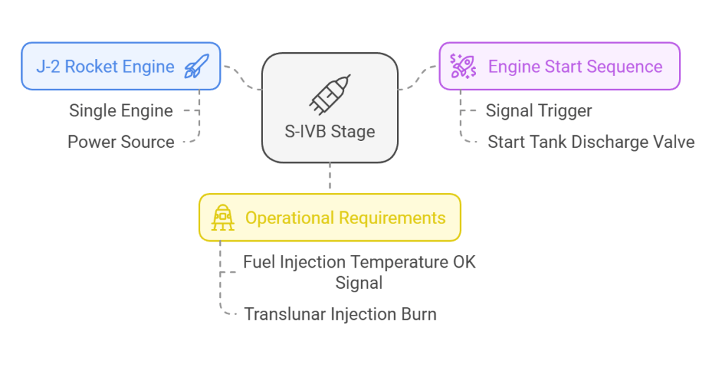
The S-IVB stage J-2 engine start sequence is similar to that of the S-II stage, with the main difference being the source of the signal that triggers the start tank discharge valve. In the S-IVB, the start tank discharge valve opens upon receipt of a fuel injection temperature OK signal rather than a stage-supplied mainstage enable signal.
Conclusion
The F-1 engine’s startup sequence exemplifies precision engineering, carefully balancing fuel flow, combustion, and turbopump activation to generate unprecedented thrust. This process, perfected during the Apollo program, remains a benchmark in rocket propulsion.
For more fascinating insights into the Apollo program and rocketry, visit Apollo11Space.com. Also, check out our YouTube channel for exclusive videos: Apollo11Space on YouTube.